Three-Phase Active Load Emulator with PWM Rectifier and 3-Level NPC Inverter
Explore a controlled three-phase power-converter load emulator that shapes grid current through a PWM rectifier and returns energy through a three-level neutral-point-clamped inverter.
Open the MP4 simulation output · Enquire about the model and research support
Research objective
Track specified active power and displacement angle at the rectifier while controlling the common DC link and measuring net exported power through the NPC stage.
Software, platform and engineering domain
Primary platform: MATLAB/Simulink & Simscape Electrical. Research domain: Electrical and Power Electronics Engineering. The video title identifies the intended workflow; the video and original model must be inspected before making quantitative claims.
Model architecture and simulation methodology
- Represent the grid-side PWM rectifier and its input filter, switches, measurements and current-reference generation.
- Implement power/phase command processing and synchronize control to grid voltage with a documented PLL or reference-frame convention.
- Connect a split-capacitor DC link to a three-level NPC inverter with neutral-point balancing consideration.
- Record rectifier P/Q, NPC export, DC-link voltages and grid current distortion with consistent passive-sign conventions.
What the video outputs should demonstrate
- Commanded versus measured rectifier active power and displacement angle
- Rectifier current THD and fundamental phase displacement
- Upper/lower DC-link capacitor voltages and neutral-point imbalance
- NPC grid-side active power and net grid import/export
Interpreting the simulation results
A well-tracked load command does not necessarily imply net-zero grid power. Compare rectifier input, NPC export and converter losses while monitoring DC-link energy accumulation.
- State the direction convention for rectifier and NPC measured power.
- Calculate THD over a stable integer-cycle window using a defined sampling method.
- Separate rectifier power tracking accuracy from the NPC export and power losses.
Suggested research comparisons
- Baseline 1: uncontrolled rectifier loading
- Baseline 2: PWM rectifier without NPC regeneration
- Baseline 3: combined rectifier–NPC active emulator
Use the same physical parameters, boundary conditions and plotting window when comparing alternative methods. Numerical improvement cannot be established from the title alone.
Project screenshot and thumbnail
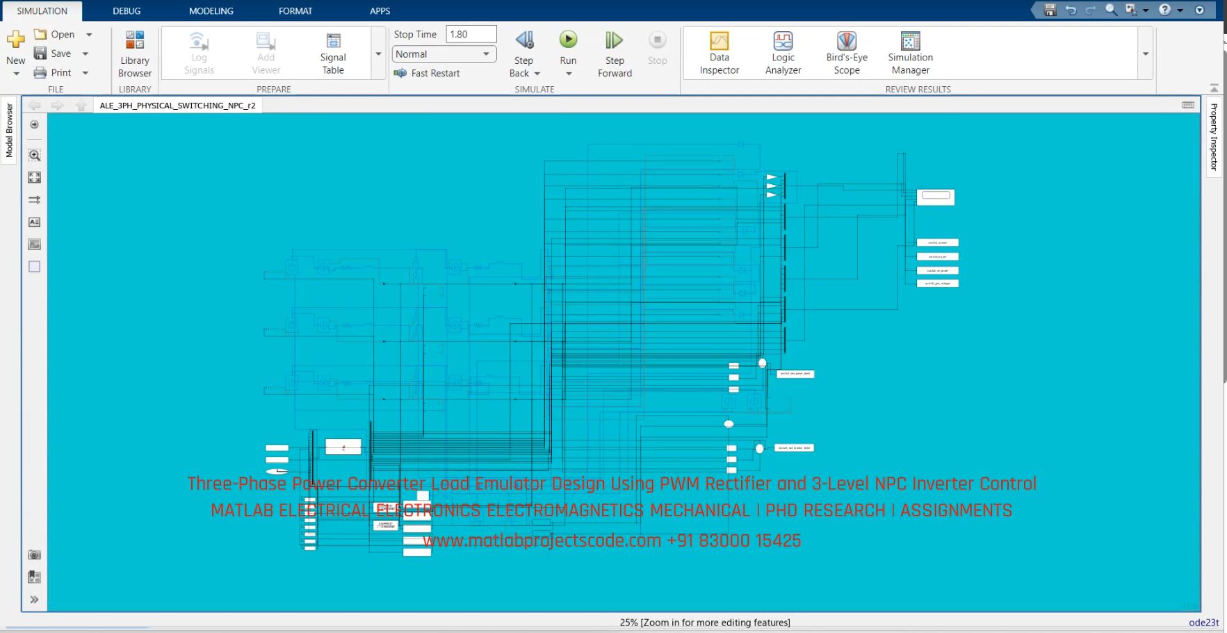
Image availability and extension must be verified on hosting before Google video indexing is assessed.
Research questions and frequently asked questions
Which software is used?
The project is associated with MATLAB/Simulink & Simscape Electrical; verify the model and solver version with the original video and source files.
Which results should be checked?
Key checks include commanded versus measured rectifier active power and displacement angle, rectifier current thd and fundamental phase displacement.
Can the video alone validate the results?
No. Model assumptions, boundary conditions and actual output traces must be reviewed before treating any simulation as validated research.
OEM and PhD research enquiries
For research model implementation, simulation verification, paper reproduction and engineering documentation across UK, Australia, Canada, US and global teams, use the contact page. Contents are for representative purposes; actual content may vary.