3D PEM Water Electrolysis Cell Simulation: Polarization, Current Density and Performance
Analyse a three-dimensional proton-exchange-membrane water electrolysis cell through voltage losses, spatial current density, reactant transport and hydrogen-production performance.
Open the MP4 simulation output · Enquire about the model and research support
Research objective
Understand how voltage, electrochemical kinetics, conductivity and transport interact to set the operating point of a PEM electrolyser cell.
Software, platform and engineering domain
Primary platform: COMSOL Multiphysics / Electrochemical Modelling. Research domain: Chemical and Energy Engineering. The video title identifies the intended workflow; the video and original model must be inspected before making quantitative claims.
Model architecture and simulation methodology
- Define anode catalyst, membrane, cathode catalyst and adjacent porous transport or flow-field regions with explicit thicknesses.
- Represent charge transport through electron- and proton-conducting domains and specify conductivity and contact resistance assumptions.
- Couple electrode reaction kinetics to species or water transport at the boundaries justified by the selected model fidelity.
- Apply a voltage or current-density sweep and check that each stationary operating point converges before continuing.
What the video outputs should demonstrate
- Cell voltage versus area-averaged current density (polarization curve)
- Ohmic, kinetic and transport overpotential contributions where resolved
- Local current-density distribution, membrane potential gradient and reaction uniformity
- Hydrogen-production estimate from current and a stated Faradaic-efficiency assumption
Interpreting the simulation results
A smooth polarization curve is necessary but not sufficient: compare its slope with the assumed loss mechanisms and check whether local hot spots or current crowding dominate the response.
- Verify current conservation at both electrodes and membrane interfaces.
- Report catalyst area, exchange current-density assumptions and conductivity temperature dependence.
- Refine mesh around catalyst and membrane interfaces and compare integrated current rather than only peak values.
Suggested research comparisons
- Baseline 1: activation-only model
- Baseline 2: activation plus membrane resistance
- Baseline 3: transport-coupled model
Use the same physical parameters, boundary conditions and plotting window when comparing alternative methods. Numerical improvement cannot be established from the title alone.
Project screenshot and thumbnail
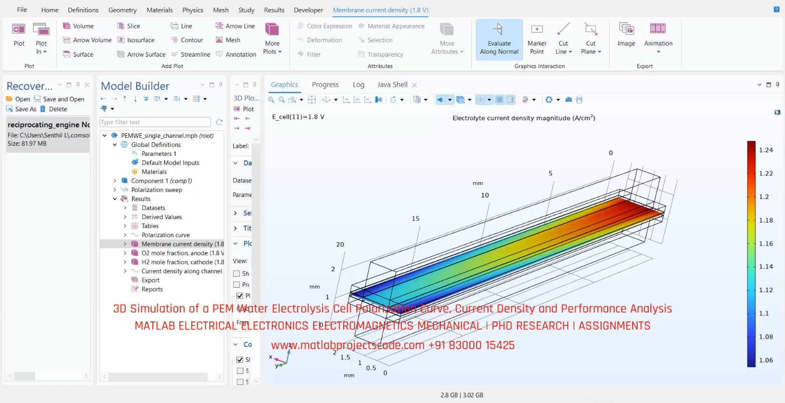
Image availability and extension must be verified on hosting before Google video indexing is assessed.
Research questions and frequently asked questions
Which software is used?
The project is associated with COMSOL Multiphysics / Electrochemical Modelling; verify the model and solver version with the original video and source files.
Which results should be checked?
Key checks include cell voltage versus area-averaged current density (polarization curve), ohmic, kinetic and transport overpotential contributions where resolved.
Can the video alone validate the results?
No. Model assumptions, boundary conditions and actual output traces must be reviewed before treating any simulation as validated research.
OEM and PhD research enquiries
For research model implementation, simulation verification, paper reproduction and engineering documentation across UK, Australia, Canada, US and global teams, use the contact page. Contents are for representative purposes; actual content may vary.