Dual-Band Shared-Aperture SIW Array and S-Band Dipole with Beam Steering in ANSYS HFSS
Study a shared-aperture dual-band antenna combining a 2×2 substrate-integrated-waveguide array and an S-band dipole, with attention to port isolation and beam-steering performance.
Open the MP4 simulation output · Enquire about the model and research support
Research objective
Establish whether both radiator functions can coexist within one aperture while maintaining impedance match, isolation and intended pattern control.
Software, platform and engineering domain
Primary platform: ANSYS HFSS. Research domain: Electronics and Communication Engineering. The video title identifies the intended workflow; the video and original model must be inspected before making quantitative claims.
Model architecture and simulation methodology
- Model the SIW via rows, cavity or guided-wave launch and 2×2 radiating-element geometry using the actual substrate stack.
- Place the S-band dipole and feed with its grounding, clearance and mechanical constraints specified.
- Use separate excitation ports and an adequately sized radiation boundary or PML.
- Sweep progressive phase states for the array and retain a consistent reference coordinate system for all far-field results.
What the video outputs should demonstrate
- S11/S22 matching and cross-port coupling across each operating band
- Co- and cross-polarization patterns for the SIW and dipole modes
- Realized gain, radiation efficiency and steering angle versus phase progression
- Scan loss, sidelobe levels and isolation sensitivity to shared-aperture geometry
Interpreting the simulation results
Strong dual-band return loss does not by itself establish good antenna coexistence; compare isolation, efficiency, beam steering and pattern distortion in both bands.
- Verify SIW via pitch, diameter and substrate permittivity against the intended guide band.
- Keep mesh and far-field normalization consistent between phase states.
- Distinguish port excitation phase from the actual radiated main-beam direction.
Suggested research comparisons
- Baseline 1: isolated SIW 2×2 array
- Baseline 2: isolated S-band dipole
- Baseline 3: combined shared aperture
Use the same physical parameters, boundary conditions and plotting window when comparing alternative methods. Numerical improvement cannot be established from the title alone.
Project screenshot and thumbnail
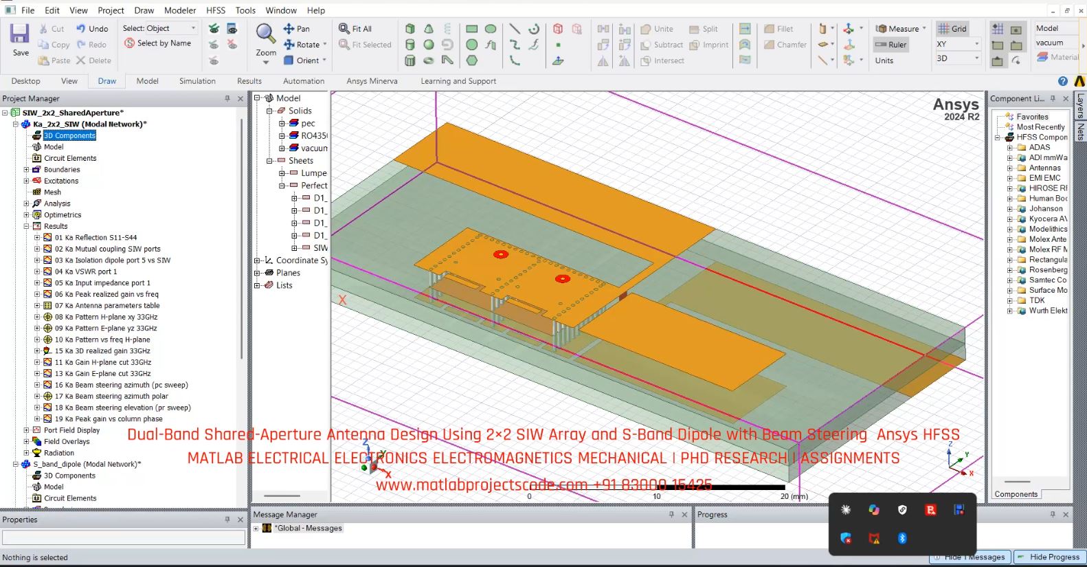
Image availability and extension must be verified on hosting before Google video indexing is assessed.
Research questions and frequently asked questions
Which software is used?
The project is associated with ANSYS HFSS; verify the model and solver version with the original video and source files.
Which results should be checked?
Key checks include s11/s22 matching and cross-port coupling across each operating band, co- and cross-polarization patterns for the siw and dipole modes.
Can the video alone validate the results?
No. Model assumptions, boundary conditions and actual output traces must be reviewed before treating any simulation as validated research.
OEM and PhD research enquiries
For research model implementation, simulation verification, paper reproduction and engineering documentation across UK, Australia, Canada, US and global teams, use the contact page. Contents are for representative purposes; actual content may vary.