Sliding Mode Observer-Based Field-Oriented Control of a PMSM in MATLAB Simulink
Examine sensorless field-oriented control of a permanent magnet synchronous motor using a sliding-mode observer to estimate rotor electrical angle and speed from measured electrical states.
Open the MP4 simulation output · Enquire about the model and research support
Research objective
Compare reference-speed tracking and torque ripple while testing sensitivity to observer convergence, machine parameters and operating-speed transitions.
Software, platform and engineering domain
Primary platform: MATLAB/Simulink & Simscape Electrical. Research domain: Electrical Drives and Control Engineering. The video title identifies the intended workflow; the video and original model must be inspected before making quantitative claims.
Model architecture and simulation methodology
- Implement abc-to-αβ and dq reference-frame transformations with consistent electrical-angle sign conventions.
- Model the PMSM, three-phase inverter, current sensing, and current and speed feedback loops.
- Construct the sliding-mode observer from voltage/current measurements; separate its switching law, filtering and back-EMF angle extraction.
- Integrate SVPWM or equivalent modulation, current PI regulators and speed control with anti-windup and saturation limits.
What the video outputs should demonstrate
- Reference versus measured rotor speed and estimated speed
- Actual versus estimated rotor electrical angle and estimation error
- d–q currents, phase currents and electromagnetic torque ripple
- Observer convergence and load-step recovery at low and medium speeds
Interpreting the simulation results
Good steady-state speed agreement can hide angle-estimation transient error. Quantify tracking and observer errors separately, then interpret torque oscillation against the current-loop bandwidth.
- Test near-zero speed separately because back-EMF-based observability can become weak.
- Recheck pole-pair scaling when converting electrical and mechanical angles.
- Compare identical motor parameters, inverter conditions and load torque across control variants.
Suggested research comparisons
- Baseline 1: sensored field-oriented control
- Baseline 2: sensorless FOC without sliding-mode observer tuning
- Baseline 3: SMO-based FOC under parameter mismatch
Use the same physical parameters, boundary conditions and plotting window when comparing alternative methods. Numerical improvement cannot be established from the title alone.
Project screenshot and thumbnail
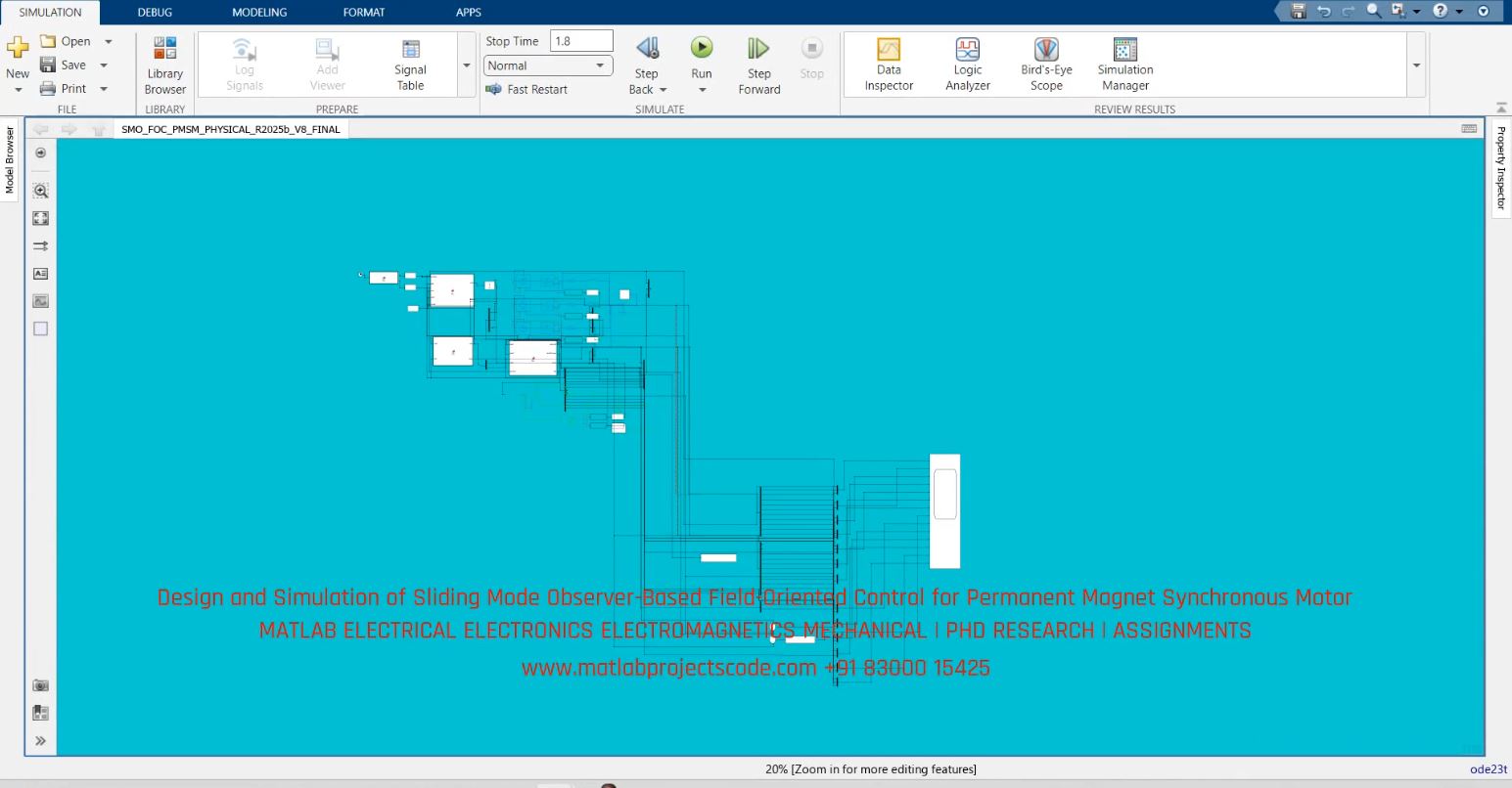
Image availability and extension must be verified on hosting before Google video indexing is assessed.
Research questions and frequently asked questions
Which software is used?
The project is associated with MATLAB/Simulink & Simscape Electrical; verify the model and solver version with the original video and source files.
Which results should be checked?
Key checks include reference versus measured rotor speed and estimated speed, actual versus estimated rotor electrical angle and estimation error.
Can the video alone validate the results?
No. Model assumptions, boundary conditions and actual output traces must be reviewed before treating any simulation as validated research.
OEM and PhD research enquiries
For research model implementation, simulation verification, paper reproduction and engineering documentation across UK, Australia, Canada, US and global teams, use the contact page. Contents are for representative purposes; actual content may vary.