Attitude and Altitude Controlled Quadcopter Using MATLAB Simulink - UAV Flight Control Simulation
UAV attitude and altitude control using MATLAB/Simulink flight-control modelling for drone research and OEM-style validation. This page is structured for engineering students, OEM teams and PhD research scholars looking for MATLAB/Simulink simulation output references, waveform explanation and model implementation support.
PROJECT_THUMBNAIL
Project Objective
UAV attitude and altitude control using MATLAB/Simulink flight-control modelling for drone research and OEM-style validation. The objective is to present a verified simulation workflow with clear output interpretation, model-study direction and project documentation support.
MATLAB/Simulink, scopes, control blocks, signal logging and waveform analysis.
PID / flight-control loop design with roll, pitch, yaw and altitude response observation under command tracking and disturbance conditions.
roll angle, pitch angle, yaw response, altitude tracking, motor command signals, trajectory response and settling-time comparison.
UAV autopilot research, drone control education, aerospace control validation, robotics demonstrations and PhD-level flight dynamics studies.
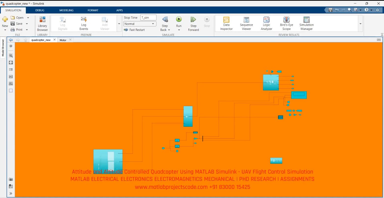
Simulation Model Explanation
The model can be used to study input command behaviour, controller response, system stability and output waveform quality. For PhD and journal-style use, the page supports methodology framing, result explanation and future scope around improved controllers, optimization or AI-based enhancement.
Important study points include subsystem arrangement, parameter tuning, signal monitoring, steady-state behaviour, transient response, settling time and comparative performance under operating condition changes.
Result Interpretation
The simulation output should be interpreted by checking tracking accuracy, overshoot, settling time, disturbance rejection and overall stability. A good result should show smooth response, reduced oscillation and clear improvement compared with open-loop or baseline behaviour.
FAQ
Can this project be used for PhD research?
Yes. It can be extended with optimization, artificial intelligence, robust control, comparative controller design or experimental validation discussions.
Can the project be modified for a university format?
Yes. Report structure, waveform explanation, block diagram discussion and thesis-style documentation can be customized.
Does the page include actual source code download?
Please contact the team for model/source-code availability and project-specific requirements.
Send the project title, required software version, expected graphs and deadline.
Request Model / Source Code →